SF-VI209M-IP - Configuration of a Master Station
For this FAQ, we have used different devices to demonstrate the reliability and ease of configuration of this system.
Door Panels
1 x SF-VIMOD-CAM-IP-BF + SF-VIMOD-KEY6
1 x SF-VIMOD-CAM-IP + SF-VIMOD-KEY6
1 x SF-VIMOD-CAM-2
Master Station
1 x SF-VI209M-IP
Displays
4 x SF-VIDISP01-7W2
2 x SF-VIDISP01-7WIP
STEP 1 - Activation of the devices
Since there are many devices, we can select all and activate them at once. The advantage is that we will be sure that the same password is configured for all devices.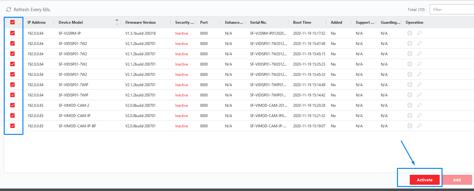
STEP 2 - Add devices to SAFIRE CONTROL CENTER
We select the device and then choose the ADD option.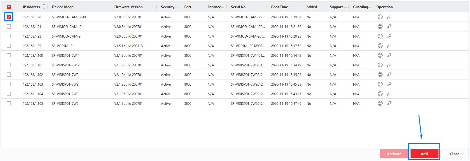
Once we have all devices associated in the top menu, we can start configuring the devices.
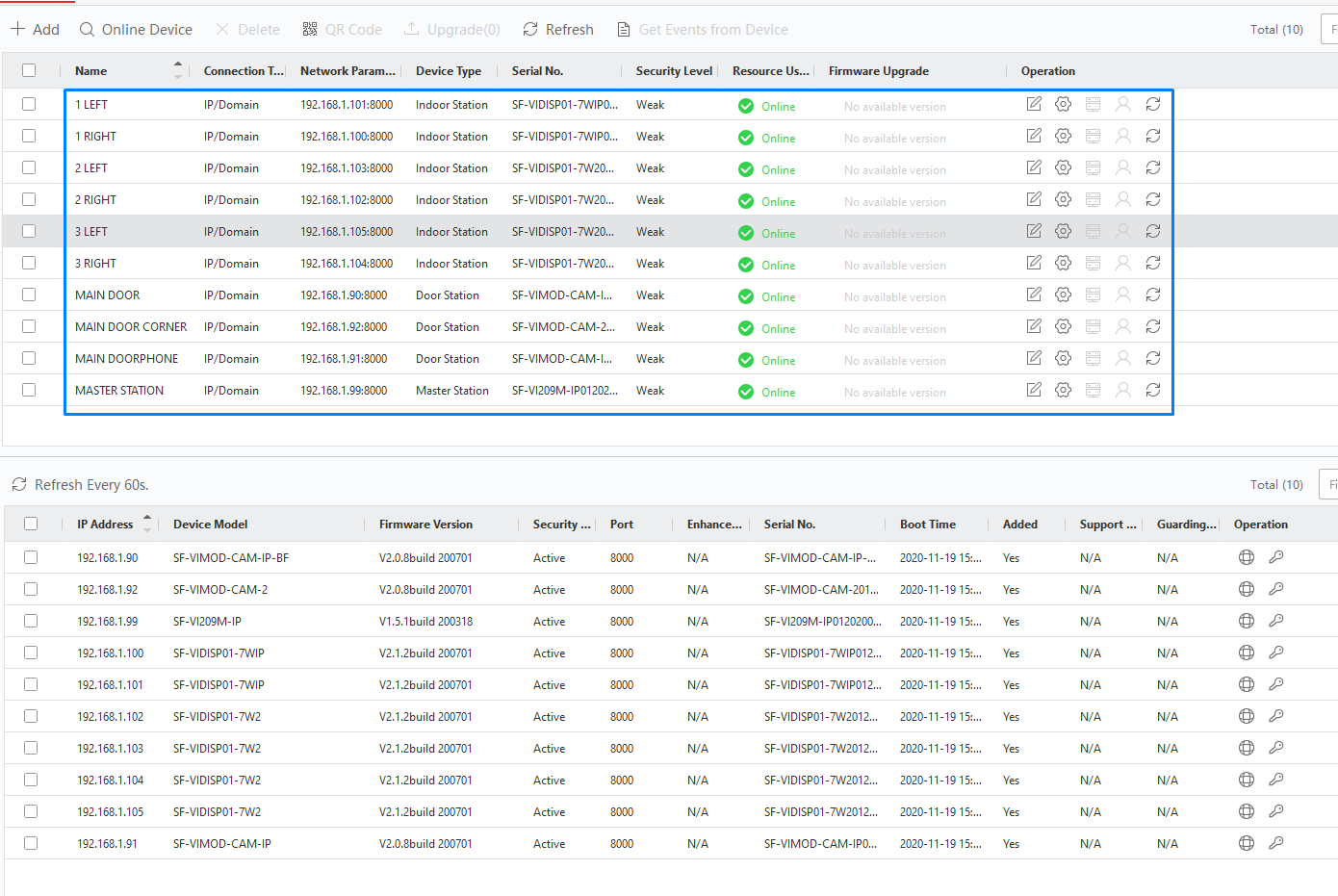
STEP 3 - MASTER STATION Configuration
The first step is to configure the master station; to do this, we click on "Remote Configuration".
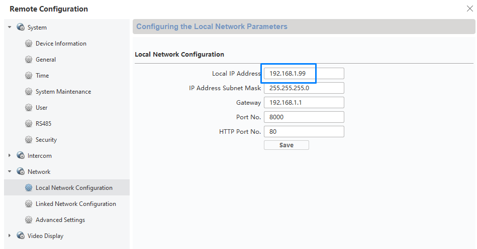
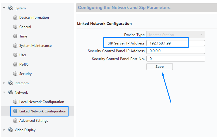
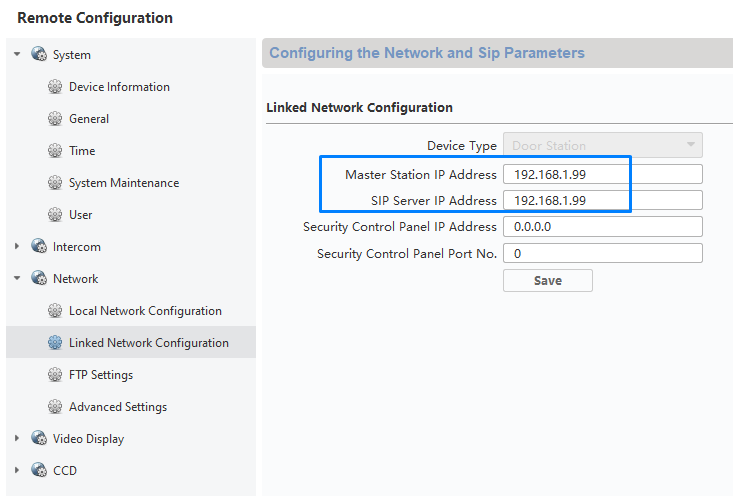
We go to the network configuration and note the IP address of the MASTER STATION; in our case, the IP address is 192.168.1.99.
Next, we go to the SIP SERVER menu, add that IP address, and save the operation, making everything look like the image below:
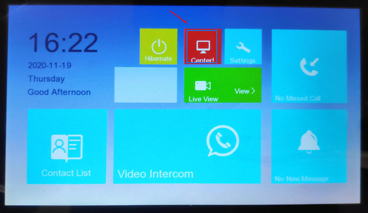
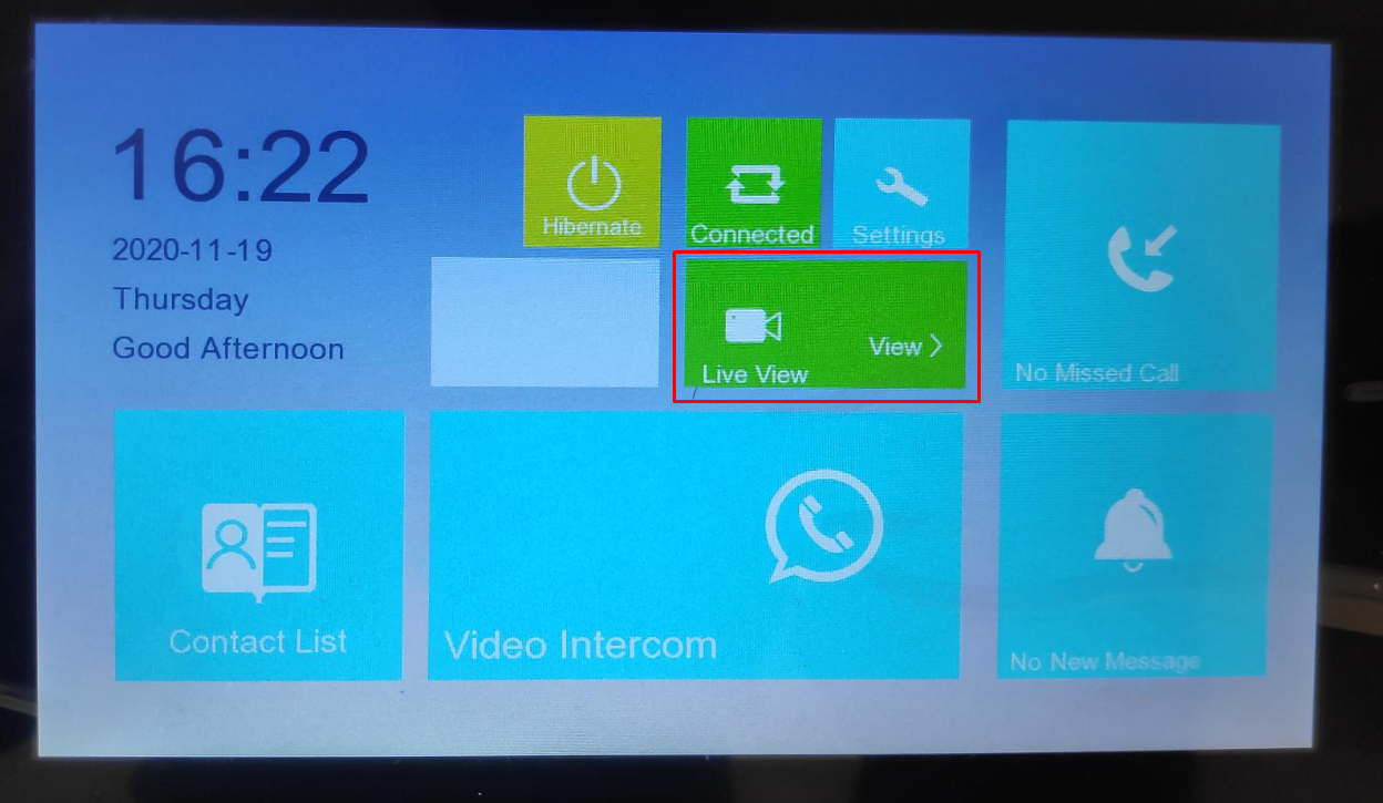
Additionally, we can verify that before changing the IP address, on the MASTER STATION screen, the CENTER icon will be RED, indicating that the SIP Server is not configured.
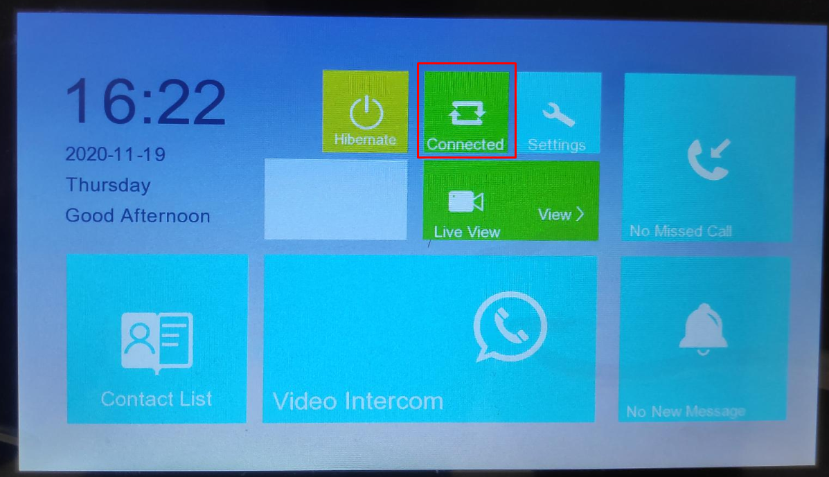
Once the IP address is changed in that field, the connection will be established.
Very important, it is also necessary to add the IP addresses of the door panels directly into the MASTER STATION; otherwise, bidirectional audio cannot be opened from the Master Station, and we will have to wait for a call from the door panel. Therefore, let's check how to add door panels to the MASTER STATION.

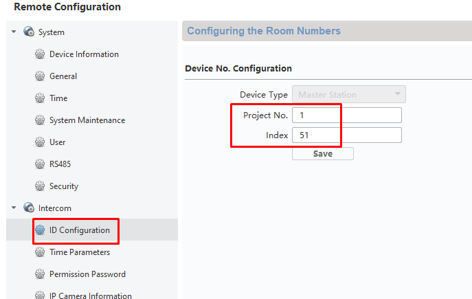
Remember, the Project number and the Index are in the menu called ID CONFIGURATION:
The configuration would be as follows:

Thus, from the MASTER STATION, we can view the MAIN DOOR panel image and also open the bidirectional audio, as well as open the door. If we did not do this, we would have to wait for a call from one of the panels.

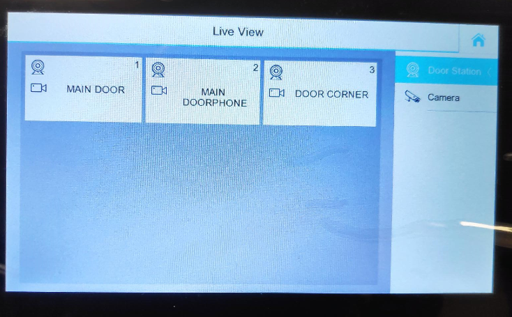
Once the configuration is done, we can check connectivity by trying to view the live video:


STEP 4 - Configuration of Door Stations
We will start with the main one. In our case, we have 3 door panels, so we will have a second panel as Secondary Door and the last door panel as slave to any of the previous ones.

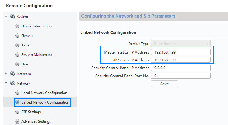
We go to the "LINKED NETWORK CONFIGURATION" and in MASTER STATION IP and SIP SERVER IP, we will enter the IP address of our master station, in our case 192.168.1.99.
Since we have 3 door panels, we have also changed the name and the DEVICE NAME / DEVICE NUMBER combination of each door panel:

We used the last part of the IP address of each panel to apply the value to the DEVICE NUMBER (by default, they have the value 88).
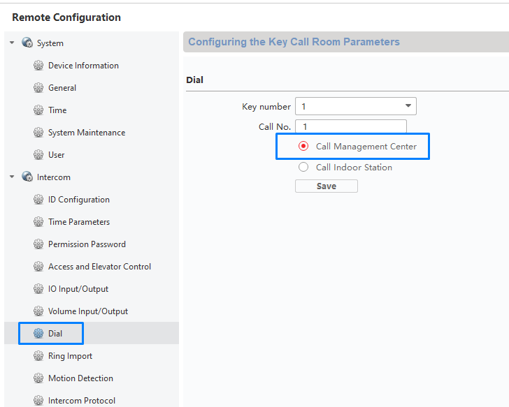
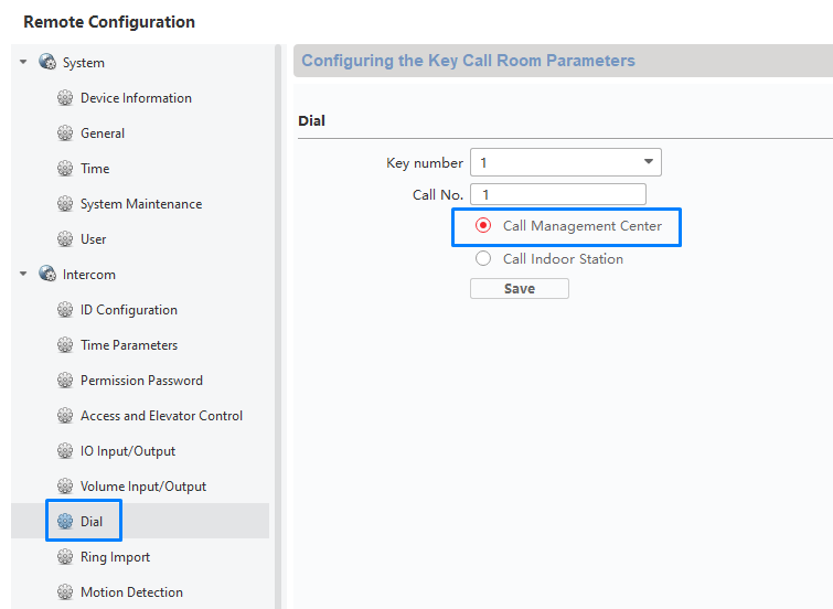
Then, in DIAL, we configure the MAIN BUTTON of our panel to call the CENTER (MASTER STATION) and not the displays.
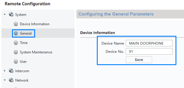
We will repeat this procedure on the MAIN DOORPHONE panel. In our case, we will imagine it is a second entrance door for the building.
The configuration will be as follows for our second door:
In the "LINKED NETWORK CONFIGURATION" settings, we apply the IP address of the MASTER STATION exactly as shown in the image; remember it is the same IP address for the SIP SERVER.
We go to DIAL and also check the option for CALL MANAGEMENT CENTER. Once saved, we can test without any problem; we will see that the call will reach the MASTER STATION.
For our 3rd panel, we will repeat the procedure. In our case, the panel does not have the SF-VIMOD-KEY6, so it only has one call button, and we will use it just to call the master station. Therefore, the configuration is the same as the other panels.
STEP 5 - Configuration of the displays
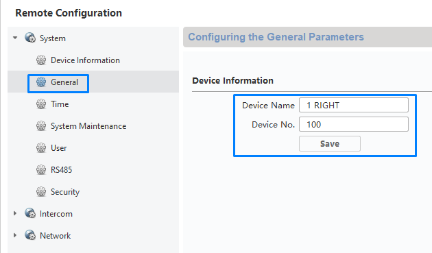
First, we will change the device name to 1st RIGHT, but we avoid special characters as they can cause issues. We will configure the ID CALL NUMBER as 100.
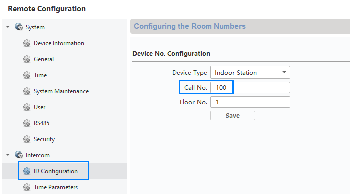
Then, in ID CONFIGURATION, we will parameterize the selected field with the number 100; this will be the number to receive calls from the external panel and from the MASTER STATION, so care must be taken not to repeat numbers.
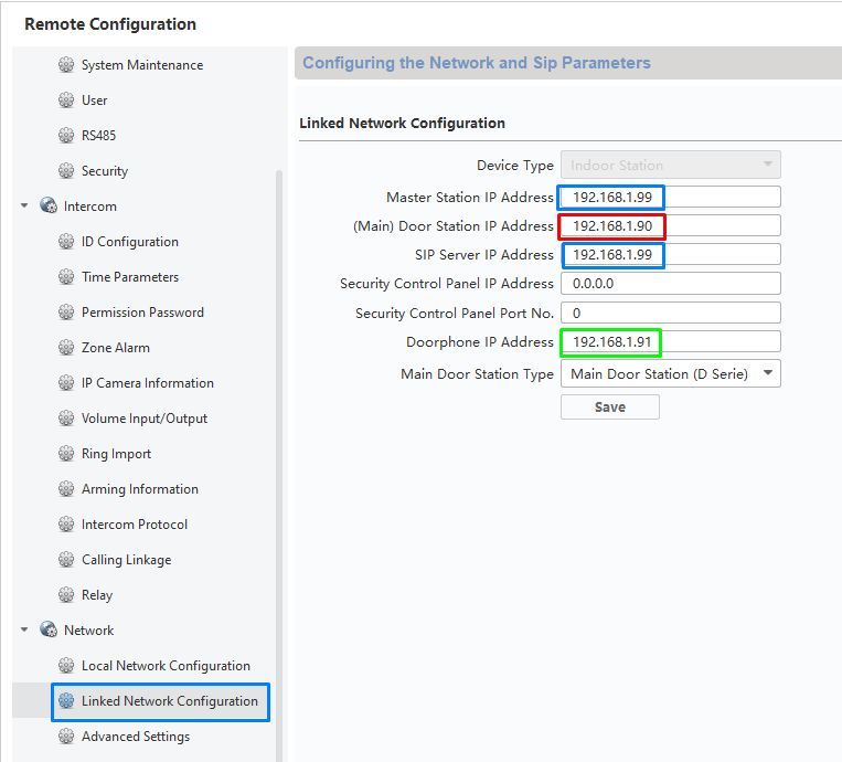
Therefore, in the LINKED NETWORK CONFIGURATION, we have to parameterize the IP addresses of our call stations.
Blue Color: The IP addresses marked in blue correspond to the MASTER STATION.
Red Color: The IP address in red corresponds to our MAIN DOOR PANEL.
Green Color: The IP address in green corresponds to our second DOOR PANEL, let's say it is a secondary door.
Remember that the IP address 192.168.1.92 is of our door panel (which will only call the master station), so there is no reason to continue with local configurations on the displays.
Once this configuration is done, we could do the following test:
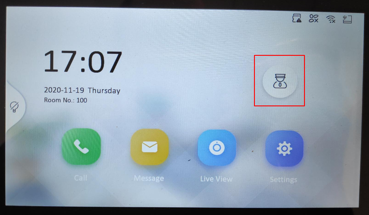
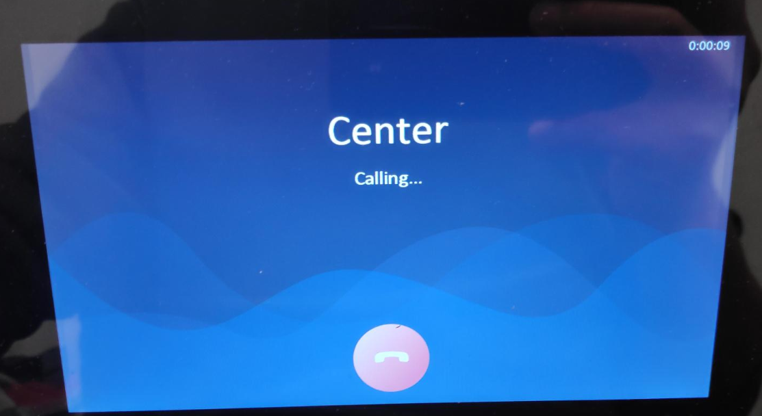
Once clicking on the marked icon, we should be able to call the MASTER STATION.
THE CONFIGURATION WE HAVE JUST PRESENTED MUST BE DONE ON ALL DISPLAYS.
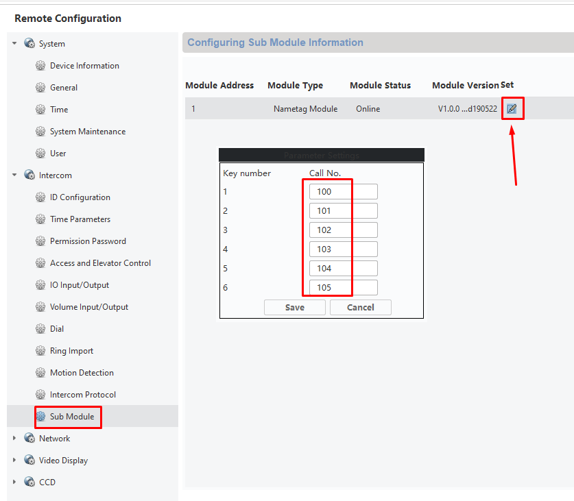
For the KEY6 module configuration, we have to go to the corresponding panels, choose the SUB MODULE option, click on Parameter Settings, and then determine that (for example) button 1 of the module will call the display with ID 100, button 2 will call the display with ID 101, etc...
Was this article helpful?
Bu bilgiler sorununuzu çözmeye yardımcı oldu mu?
Still need help?
Uzman ekibimiz size yardımcı olmak için burada.