SAFIRE - Configuration of SF-VIK001 (IP or 2-wire) from SAFIRE CONTROL CENTER
How to configure the 2nd Generation SAFIRE video door entry systems from remote settings on the screen.
This FAQ is valid for the SF-VIK001 KITS.... (IP or 2 Wires)
Firmware version installed in the devices:
SF-VIMOD-CAM-IP: V2.2.45 build 210519
SF-VIDISP01-7WIP: V2.1.20 build 210519
For the configuration it is recommended to use the most updated version of SAFIRE CONTROL CENTER; we remind you that it is possible to download it directly from the Visiotech website.
Step 1 - Activation of the devices:
The SAFIRE video door phones are by default INACTIVE, so they must be activated.
The activation method consists of assigning a password to the device.
Step 2 - Change the IP address of the devices
After activating the outdoor station and the indoor station, we proceed to apply an IP address to both devices, according to the range of the client's router.
Once we have the two devices initialized and with the IP addresses correctly specified, we will proceed to add them to the SAFIRE CONTROL CENTER.
Step 3 - Adding the devices to the SAFIRE CONTROL CENTER
Select the device, click on ADD and, in the new window, configure the name, the port (it is 8000 unless we have changed it before), the user (it is admin) and put the password that we have used in the product ACTIVATION. The IP address will appear automatically.
It is recommended to check the time synchronization box.
Step 4 - Configure the system
Basically the configuration consists of adding the IP address of the external station to the monitor, nothing else.
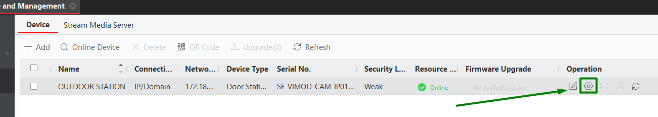
To do this click on "Remote Configuration" (gear icon):
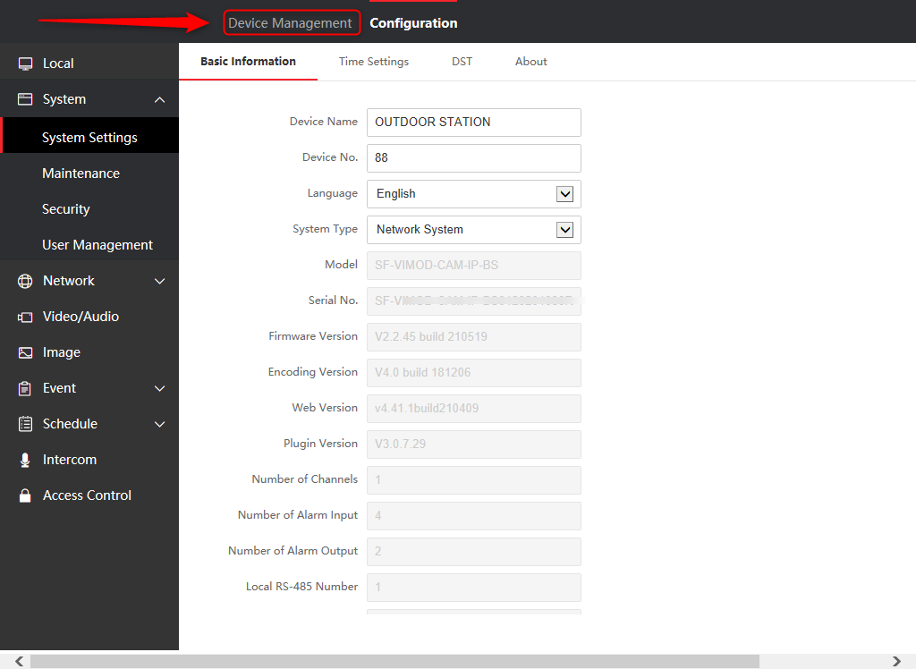
Once the device has been added to the Software, we can alter its parameters and make several more advanced adjustments.
To do so, click on "REMOTE CONFIGURATION"
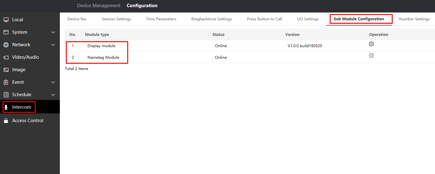
The next step is to configure the module by accessing the Sub Module option and then click on"Settings" (In our example we have 2 modules, so both appear).
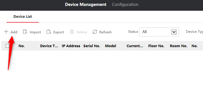
The next step is to add the monitors to the video door entry panel, there are several ways to do it, but we are going to dedicate this FAQ to do it from the video door entry panel itself.
To do this, click on "DEVICE MANAGEMENT".
Then click on "ADD"
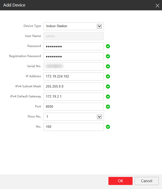
Then we will have to enter the data of our first screen, this procedure will have to be repeated for each number of screens, if we have 10 screens, we will have to repeat it for each screen.
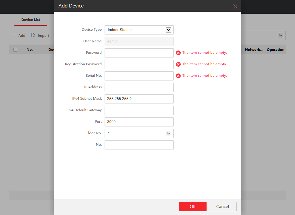
- We recommend that the password be the same as that of the video door entry panel.
- The SN must be the serial number of the screen.
- Configure the IP (make sure the IP is free to be used)
- Port 8000 (default)
- Floor number (The number of the floor of the apartment)
- Room Number (The number of the screen)
Very important to check the SN and Room Number, write down if necessary.
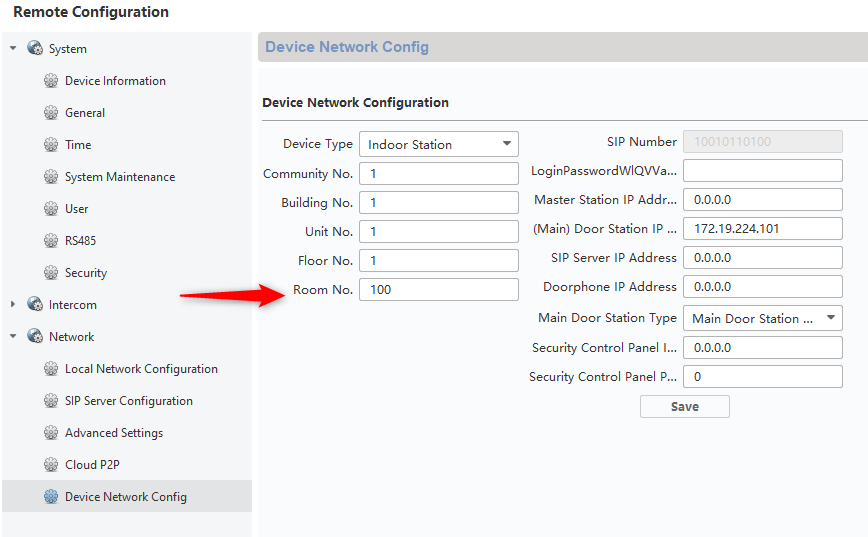
If necessary, we could confirm if the screen really has the Room number 100, by accessing the screen settings.
Once these steps have been completed, the system will be configured.
Was this article helpful?
Bu bilgiler sorununuzu çözmeye yardımcı oldu mu?
Still need help?
Uzman ekibimiz size yardımcı olmak için burada.